
Procedure for PWHT method by internal oil firing Method
INTRODUCTION AND GENERAL DESCRIPTION
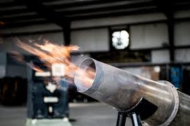
This procedure relates to the application of high velocity oil fired technique for stress relieving of Applicable Thicknes walled vessel by in-situ heat treatment to achieve stress relief temperature of 620°C the mode of heating will be by using high velocity burner.
The heat treatment specifications and temperature constraints as per ASME Section VIII Div 1. The vessel should have provision to enable free expansion & contraction of the vessel. The vessel shall be placed on a platform 1.5’ above the foundation or shall be placed on the ground level (uniform flat surface) Uniform flat surface is very essential to ensure smooth expansion /contraction of the vessel during heating/cooling. The vessel shall be supported with minimum radial support.
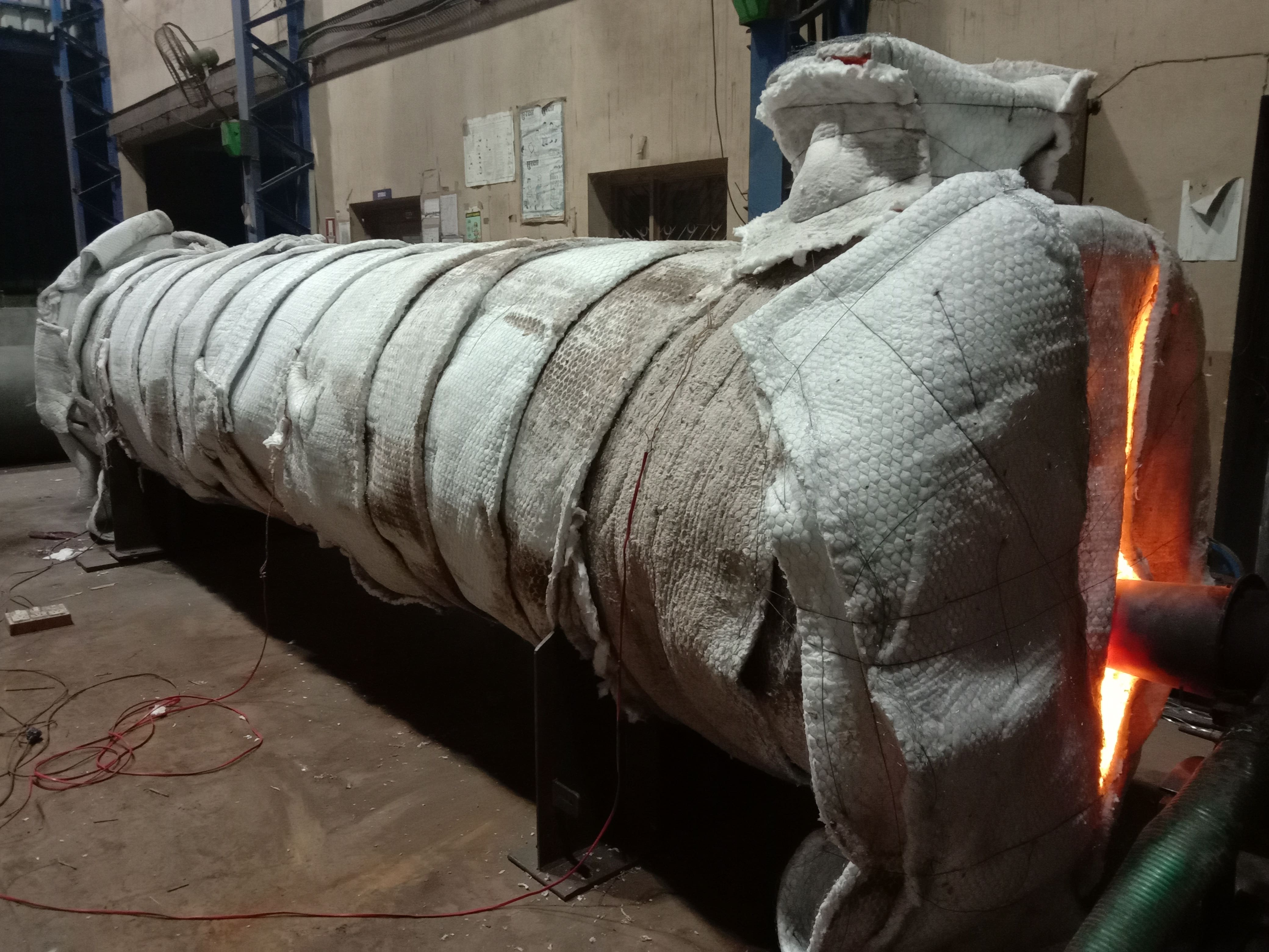
The vessel is insulated with 25mm Thk MMTCL CERAWOOL BLANKET 96 having a density of 96kg/m3 on it’s exterior surface. Before final placement of the vessel either on platform /supports, 1 layer of CERAWOOL shall be laid on ground/support , so that the base of the tank rest on the insulated ground/support. The high velocity burner with angled/straight cones will be inserted from the manhole/ nozzle opening . The products of combustion are exhausted through nozzles. The burner position across the vessel is such that circular of hot flue gases is created inside the vessel, which ensures excellent temperature uniformity across the tank. The high velocity of the burner produces a scrubbing action on the shell surface, increasing the temperature uniformity. Care is taken to ensure that there is no flame impingement on any part of the tank. The high velocity burner will be controlled manually by continuous monitoring of temperature recorder. Control of temperature will be done by manual adjustment of oil flow/pressure and by butterfly valves of blower (combustion air). The turndown ratio of the high velocity burner is to the tune of 20:1 that gives high degree of control at all stages of firing. As the primary flame of the burner is enclosed in the main combustion chamber, at no time, the flame impinges on the vessel surface , totally avoiding hot spots. Exhaust gases will be taken out from the small nozzle opening at the dishend side. Temperature will be monitored & recorded at regular intervals of time & the heat treatment cycle will be controlled accordingly. After completion of heat treatment cycle, duly certified time - temperature chart will be submitted to the client.
JOB SPECIFICATION
The heat treatment described within this procedure is based on client requirement.
POST WELD HEAT TREATMENT SPECIFICATION
Unrestricted heating rate up to 300°C Heating rate of maximum 100°C/Hr. With a temperature differential of not more than 70°C between thermocouples. Soaking temperature of 620°C +/- 20°C. Soak Duration 2hr and 30min Cooling rate of maximum 70°C/Hr. with a temperature differential of not more than 70°C between thermocouples. Unrestricted cooling rate from 300°C
Temperature constraints
Based on the above heat treatment specification, the temperature constraints, applicable per API 650 will be followed as under.
| Maximum Differential Temperature | |
|---|---|
| Constraints-1 All thermocouple below 300°C | Unrestricted |
| Constraints-2 All thermocouple above 300°C | +/- 30°C |
| Constraints-3 All thermocouple during soak period | 620°C +/- 20°C |
| Constraints-4 All thermocouple below 620°C | +/- 30°C |
| Constraints-5 All thermocouple below 300°C | Unrestricted |
EQUIPMENT Combustion equipment details for internal oil firing method
- Burner type: 1 no. 02 no .High velocity Burner.
- Fuel : HSD (diesel)
- Mounting of Burner: will be fired through manhole with appropriate straight or Angle cones per nozzle orientation.
- Blower : 5hp Ignition : with the help of flame Burner management train : comprises of HSD flow control valve, oil pressure regulator ignition transformer.
- Compressed air line FRL & control valve unit & LPG pilot ignition system with line.
Temperature control
- The high velocity burners will be controlled manually by continuous monitoring of temperature recorder.
- Control of temperature will be done by manual adjustment of HSD flow/pressure and by butterfly valves of blower (combustion air )
- The turndown ratio of high velocity burner is to the tune of 20:1 which gives high degree of control at all stages of firing ,as the primary flame of the burner is enclosed in the main combustion chamber & at no time ,the flame impinges on the vessel surface , totally avoiding hotspot.
SITE ELECTRICAL POWER REQUIREMENTSl
The electrical power requirement within 3metres of our equipment at site is 415 volts,3 phase , 4 wire , 50Hz supply of following capacity.
- Combustion air blower : (5 Kw x 2) = 10.00Kw
- Pump and other accessories (approx) = 8.00Kw
- Lighting and other (1 Kw) = 1.00 Kw
TEMPERATURE RECORDING
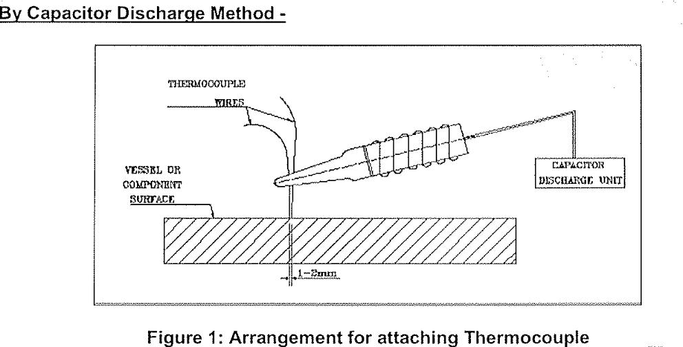
1. The thermocouple wire (T/C) will be CR-AL i.e. K type 1/22 swg , which will attached to the vessel by thermocouple attachment unit.
- Identify the area where the thermocouple to be attached
- Clean the area with emery paper
- Charge the capacitor
- Both the thermocouple shall be directly welded on the surface of weld joint and maintain 1 to 2 mm of distance between two wires of thermocouple.
- Catch the thermocouple place it to proper location and weld with capacitor discharge welding as per the WPS- CDW01 REV 0.
2. Copper constantan compensating will be used for the connection between wire and temperature recorder. The copper lid (+ ve) will be connected to the cr-conductor (non magnetic) and the constantan lead (- ve) lead to the NI-AL conductor (magnetic).
3. Each thermocouple will be connected to a calibrated continuously monitoring temperature recorder, thus providing temperature chart print out giving information on temperature variations and trends during the SR cycle.
4. The chart will be presented as a record of the heat treatment cycle. The recorder will be adjusted for a range of 0°C - 1200°C with appropriate chart speed.
5. Last calibration certificate of the thermocouple wire and temperature recorder will submitted at the time of meeting.
6. The thermocouple location on the vessel will be as per Drg.No.
STRESS RELIEVING PROCEDURE
- Before final placement of vessel on saddle supports or on platform , 1 layer of cerawool ,25 mm Thk . Insulation material of density 96 kg/m3 shall be laid on ground/ support, so that the base of the tank rest on the insulated ground /support. Then the entire vessel shell and roof will be externally insulated with one layer 25 mm Thk 15% overlapping insulation material of density 96 kh/m3 . The insulation mats will be plugged before in chicken wire mesh. All the gaps between the insulation mats will be plugged before SR.
- Thermocouple will be located circumferentially as per codes requirement & staggered. Thermocouple will be attached to the vessel as described above.
- 02 nos. High velocity burner (HSD fired) will be inserted from manhole openings available on vessel. The approx amount of HSD require for stress relieving shall be 22 liters per ton weight of vessel.
- 02 nos. High velocity burner (HSD fired) will be inserted from manhole openings available on vessel. The approx amount of HSD require for stress relieving shall be 22 liters per ton weight of vessel.
- The combustion equipment will comprise of burner, blowe, flexible hoses, and control station.
- Heat cycle profile control will be achieved by controlling fuel flow and combustion airflow through regulating valves
RESOURCES AND PERSONNEL PLAN
Site organization & Manpower Planning
- Project manager
- Site Heat treatment supervisor.
- Heat Treatment Technician cum Operator (Site).
- Helper as and when required.
Equipments List
- For above work will mobilize 2 sets of High velocity Burner system.
- 06 point Temperature Recorder as per require.
- Oil pump : 02set
- Wire type Thermocouple
- Reading cable
- Too Box
- Thermocouple Attachment Machine
DOCCUMENTATION AND RECORDS
Site supervisor will be appointed to liase with the client site representative and ensure compliance of procedural requirements. The site supervisor responsible for all documentation.
The documentation will comprise of the following
- Details of thermocouple lay out.
- Heat treatment record sheet as applicable.
- Time temperature chart with details of heat treatment specifications, job specifications, chart speed, date of operation etc
- Record and thermocouple calibration certificates.
SAFETY
- All burner and associated equipment will be checked and test fire prior to dispatch to site.
- The site engineer will be designated as the safety officer on site to ensure that all site operation is carried out in accordance with accepted safe working practices. He will be responsible to ensure that all site safety requirements are fully met and complied.